What Is a Curve Tracer?
A curve tracer is a piece of high voltage testing equipment, used primarily in a manufacturing facility’s quality control laboratory. It subjects an electronic component to either a continuous, or stepped, range of power inputs to determine the component’s performance, efficiency or tolerances. The resulting output data from the component is typically plotted on a graph as a curve, which gives the instrument its name.
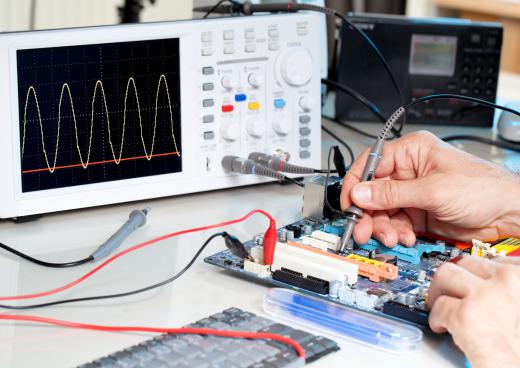
The principles and operation of a curve tracer are quite straightforward. A testing target, such as a diode, transistor or switched thyristor, is inserted into the machine. This step may be delicate because modern electronic components are microscopic, solid-state semiconductor circuits. The machine is capable of introducing precise power, a mix of voltage and amps, to the circuit’s input terminal. The circuit’s output terminal is ported through an oscilloscope to measure the change in the power as displayed in waves of voltage and amplitude.

A targeted component is called the device under test (DUT). The earliest curve tracers tested the electrical circuits built within sterile vacuum tubes and displayed their output on an oscilloscope for the operator to analyze and record. Modern tracers still display this, but are also equipped with computers to automate the testing process and compile the results.
The basic measurement of a curve tracer is input voltage against output current, or V-I. The X-axis of the graph is the equipment’s power; the Y-axis is the DUT’s output signatures. Among the conclusions which can be readily drawn from the curve is voltage leakage, a measurement of the circuit’s efficiency. For diodes for alternating current (DIAC) thresholds, the X-Y curve will clearly verify the precise voltage that triggers the diode’s on-versus-off state. The curve tracer can also reverse +/- polarity to identify defective circuits and localize sources of interference.
Components with resistor gates, and components requiring a third input current, can be similarly tested with all modern testing equipment. They can also spatially display the curve in an X-Y-Z grid, but diagnostically, they are manually intensive, requiring stepped control of voltage input. Testable electronic components include triodes with alternating current switches (TRIAC) and thyristors with gated switches. Most equipment can also test two circuits simultaneously, useful for evaluating performance by comparison.
Different models of the testing equipment vary according to the maximum voltage they are able to generate and channel to their very small terminals. Some units are rated at up to 2,000 volts. The high voltage and the resulting heat present a safety hazard for operators of curve tracers. The incorporation of computer interfaces to the testing equipment has automated processes and allowed operators of some models to safely control them remotely.
AS FEATURED ON:
AS FEATURED ON:


Discuss this Article
Post your comments